
UniLOR® N Single-layer Lift-off Photoresist
Part of the StructSure® Line
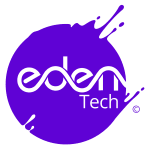
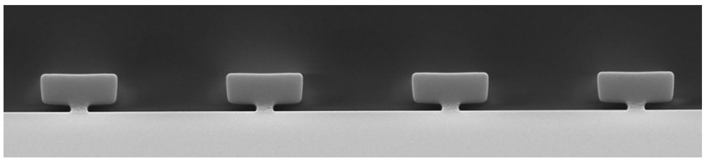
Single-layer Lift-off Deposition
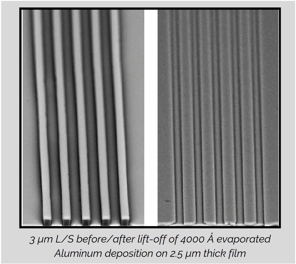
3 μm L/S in 3 μm thick UniLOR® N
Key Features
- Negative tone, chemically amplified resists
- 1 to 5 μm film thickness range
- i-Line/Broadband sensitivity, 1:1 aspect ratio capability
- Adjustable sidewall profile angle
- Aqueous alkaline development (standard 0.26N TMAH developers)
- Suitable for metal evaporation physical vapor deposition processes
- Pattern thermal stability up to 200°C
- Clean removal with standard photoresist removal chemistries
- Suitable as top imaging resist in bi-layer lift-off processes
Application Notes
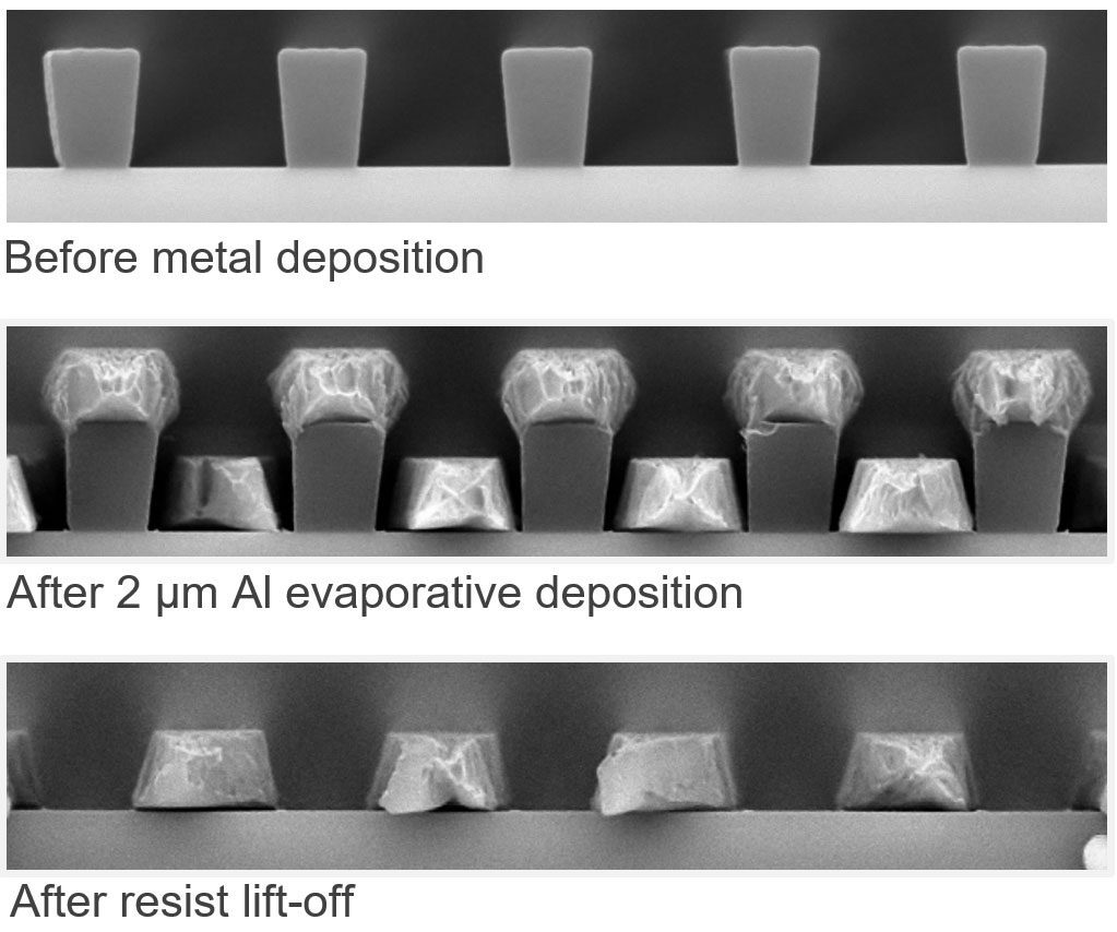
Wall Profile Adjustment through Exposure Dose and PEB
3 μm film thickness – 3 μm L&S
High Temperature Bi-Layer Lift-off Processes
Bi-layer resist stack post 200C/1h hot plate bake,
6 μm L/S – 2 μm UniLOR® N on top of 0.5 μm LOR C
1.98 μm undercut
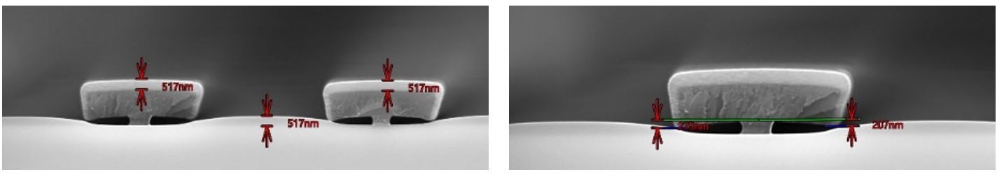
Bi-layer resist stack post 200C/1h hot plate bake,
6 μm L/S – 1.5 μm UniLOR® N on top of 0.5 μm LOR C
2.1 μm undercut
Process Parameters
Coat
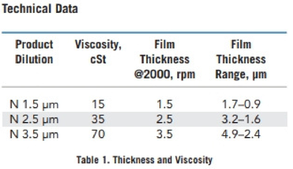
UniLOR® N resist is available in three standard viscosities that range in film thickness (Table 1). The film thickness vs. spin speed curves are displayed in 1A, 1B and 1C for various air flows. The curves were generated using static dispense on 6″ (150 mm) silicon wafers and a soft bake of 115°C on a level hot plate. Please note that the exact thickness obtained may be slightly offset from curves in Figure 1 due to equipment type, setting differences and room conditions, as demonstrated by varying exhaust level. For clean lift-off processing, LOR/PMGI films should be thicker than the deposited metal film, typically by 33%.
Recommended Coating Conditions
- Dispense: Approximately 1 ml of UniLOR® N per inch (25 mm) of substrate diameter
- Spread Cycle: Spin to 500 rpm for 5 –10 seconds with acceleration ramp of 500 rpm/second.
- Spin Cycle: Ramp to final speed with acceleration of 500 rpm/second and hold for 30 seconds.
Soft Bake & Edge Bead Removal
The primary function of the soft bake process is to dry the UniLOR® N film. A 115°C soft bake for 2 minutes on a level hotplate with good thermal control and uniformity is recommended. UniLOR® N film typically remains slightly tacky after soft bake.
During the spin coating process, a build-up of photoresist can occur on the outer edge of the substrate, especially for thicker resist coatings. Although an edge bead has not been observed in UniLOR® N film, it can be removed by directing a small stream of Kayaku Advanced Materials’ EBR PG at the edge of the wafer. An edge bead removal step can be done immediately following soft bake using Kayaku Advanced Materials’ EBR PG. A 65°C bake for a minimum of 1 minute is necessary to drive off any remaining solvent following EBR. For edge bead removal using EBR PG, please refer to the EBR PG technical data sheet.
Exposure
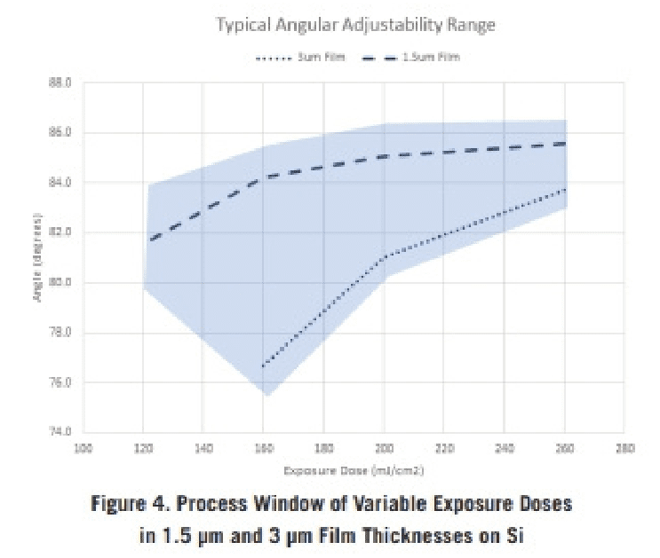
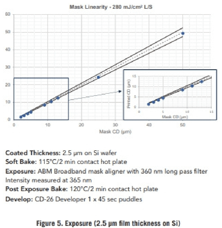
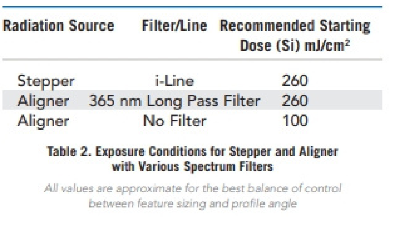
UniLOR® N is optimized for near UV (350-450 nm) exposure. The exposure dose is a critical lever for controlling the profile angle. Higher or lower exposure doses will promote more or less crosslinking, respectively, in the following PEB step. By extension, this will also set the foundation for the angular profile of the resist. Exposure conditions are listed for multiple exposure wavelength ranges and sources in Table 2. Together, Figures 4 and 5 provide a processing window that will help with determining an ideal process under 365 nm long pass filter and i-Line (on Veeco Ultratech Stepper, Figure 6.) exposure.
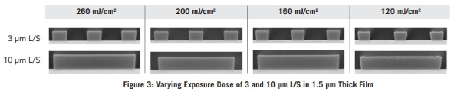
Feature under sizing associated with exposure and PEB are typically observed. The higher the dose, the closer sizing approaches 1:1 as shown in Figure 3 3 μm L/S. Features typically undersize from 0.5 μm to 1.25 μm as exposure dose is lowered. Under sizing may be corrected by increasing exposure dose, PEB temperature or by using a compensating mask with adjusted feature sizing. Ultimately, a matrix design varying exposure dose and PEB temperature is recommended to fine-tune the profile angle.
Note: While using hard contact alignment, the mask has been observed to occasionally stick to the film with no detrimental effects observed in the desired profile.
Development
UniLOR® N resist is compatible with TMAH based developers, including surfactant and surfactant-free variations. Development methods such as immersion, spray, puddle or spray/puddle may be used. Process optimization is necessary for different developer chemistries to achieve desired performance. Once optimized, it is a quick and simple process. A recommended spray/puddle step uses 2.38% TMAH (0.26N) at 23˚C for one 45 second developer puddle.